Build Log

Motivation
2020 had just finished, Melbourne had emerged from its first year of COVID lockdowns, and it was summer in Australia. I was meeting up with a friend, David (todo handle), another keyboard fan, who I’d been trying to convince of the joys of trackballs. He’d recently borrowed my Kensington Expert Mouse (a trackball). He mentioned that he liked it, but he wished it had a bit more travel- meaning he wished he could spin the trackball and see his mouse cursor fly accross the screen- as it was, it was a bit “sticky”.
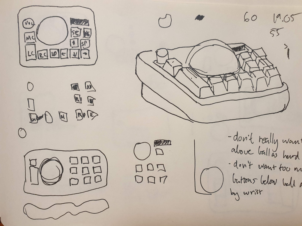
I’d just finished up my writeup of my Oddball keyboard, so I was ready for a new challenge. David mentioned he was interested in starting a keyboard shop. With the stars aligned, we decided to tackle a new project. We’d aim to make a trackball that took on aspects of the mechanical keyboard world:
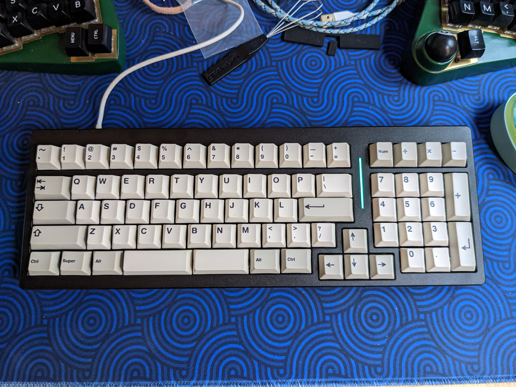
- Keyboard style switches and keycaps (as opposed to trackball/mouse style micro-switch)
- Premium look and feel; something like CNC’d aluminium
- Standard trackball size (pool ball), so the ball could be easily changed, similar to how keyboard enthusiats like to switch out their keys
- OLED screen for information and feedback
- Encoder to control trackball sensitivity
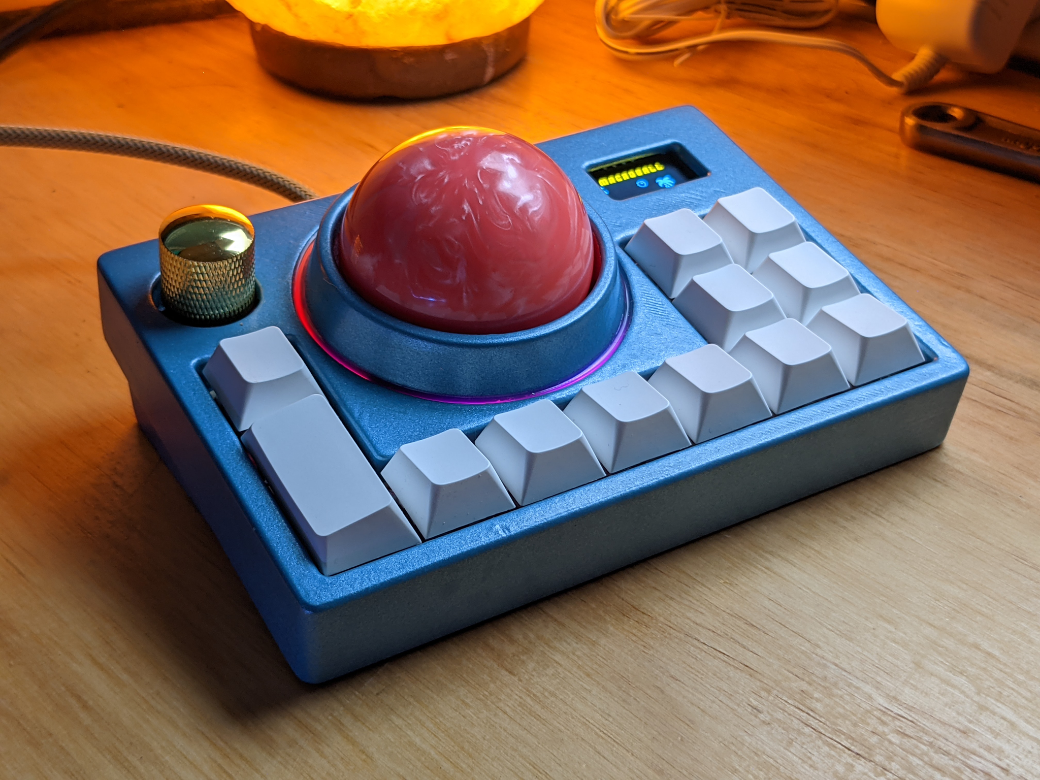
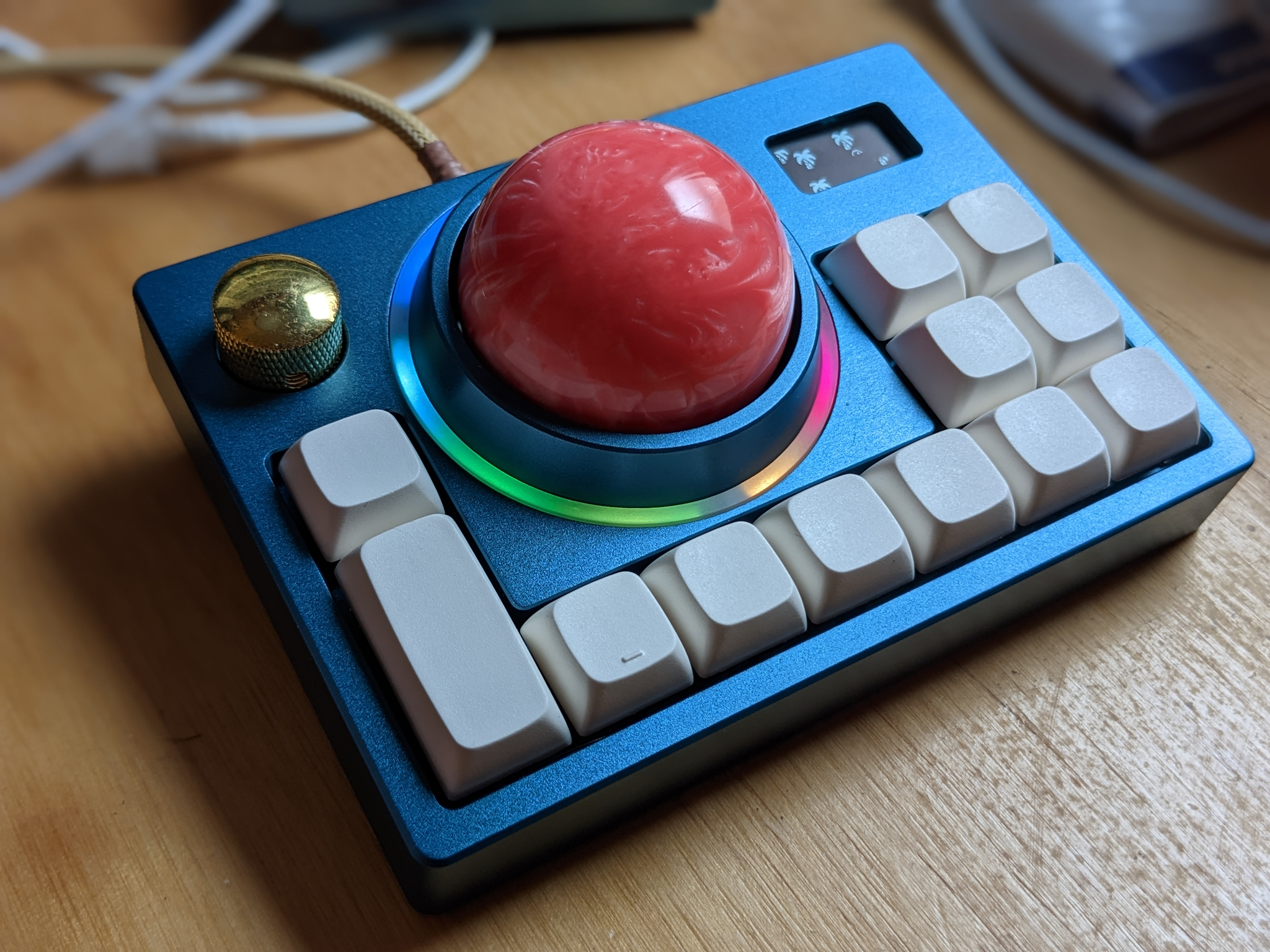
TL;DR: we were aiming to create a premium style macropad with a trackball.
Prototype week
A week later, my family met David and his partner at the beach. He brought his Planck, and I brought some 3D prints, and we tried to not get sand in anything. I tried out his latest build; it felt good. It was two years ago, but I can still remember the feel of IFK BoH hammering down on aluminium at 32°C/90°F. He tried the 3D prints of the macropad. They were rough, and somehow had got blood on them during assembly; but they also felt good. We decided to forge ahead.
First prototype build
With a bit of leave and some enthusiam, we got together a couple of PCB designs. We are by no means experts, but between ai03’s keyboard design tutorials (I think a few of us have been there), and my past experience with the Oddball, we were able to come up with a solution.
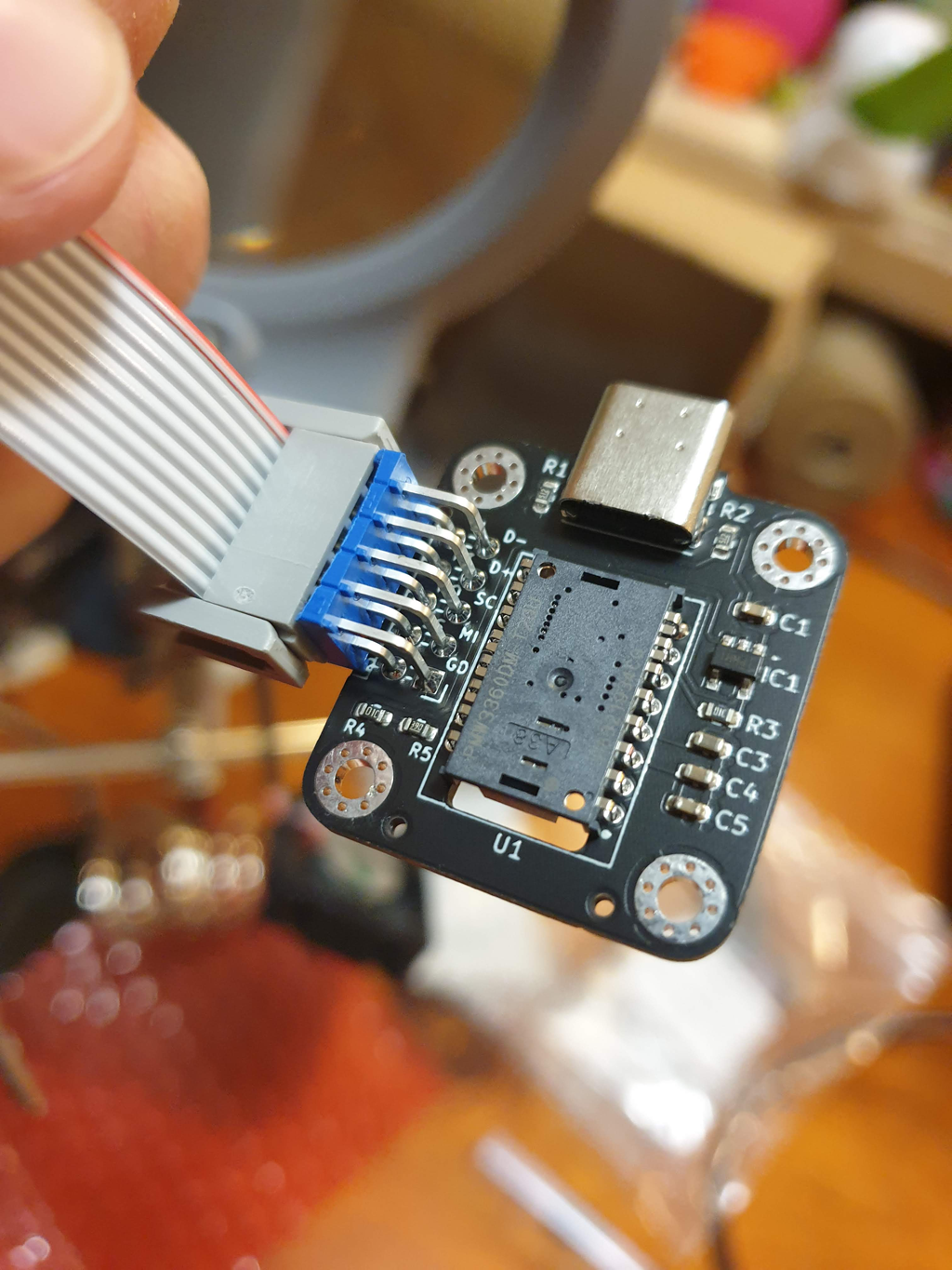
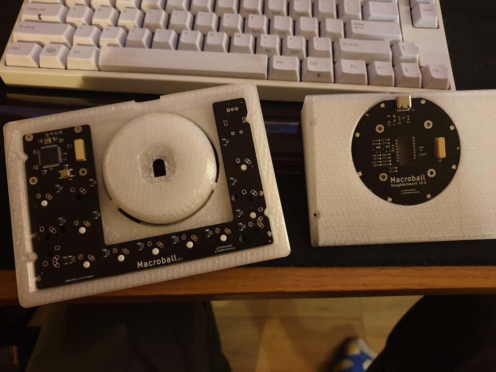
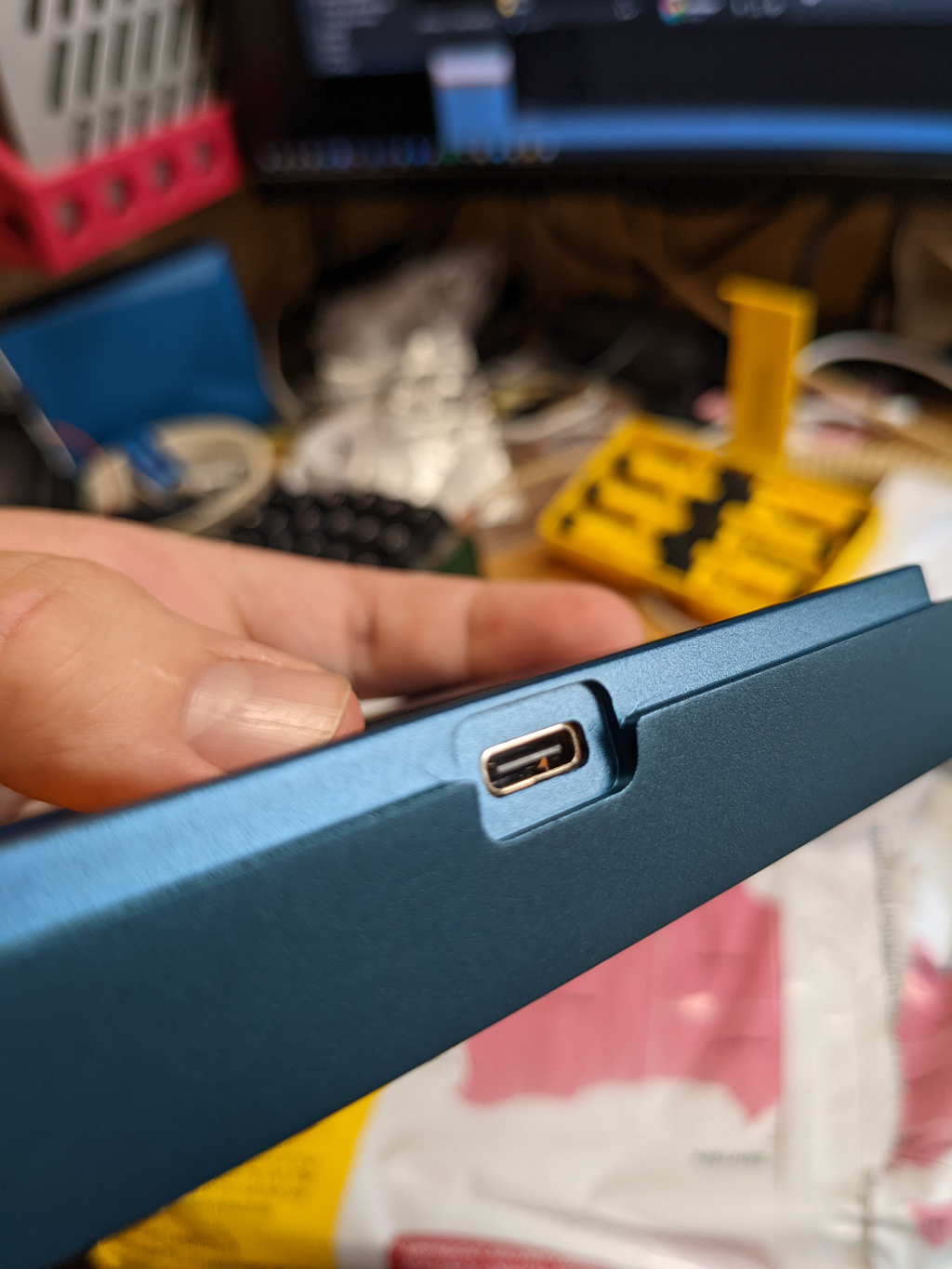
We settled on a pair of PCBs. The smaller board (daugherboard) would connect to the USB cable, and also house the PMW3600 motion sensor to track movement. This would connect via an 8 pin cable to a larger board, which would house the ATmega32U4 (a commonly used keyboard controller), along with the key switches, OLED display and encoder.
Initially we just sent for the daughterboard, as this was the novel twist on the keyboard design, and we wanted to check it worked. After hooking it up to a Pro Micro, we could seen mouse cursor movement: it was alive!
Firmware
At some point (2021 is a blur), my 3D printer had a few health issues, so I decided to work on the firmware for a bit. I leveraged the open source QMK firmware/code, which is easy to modify and extend.
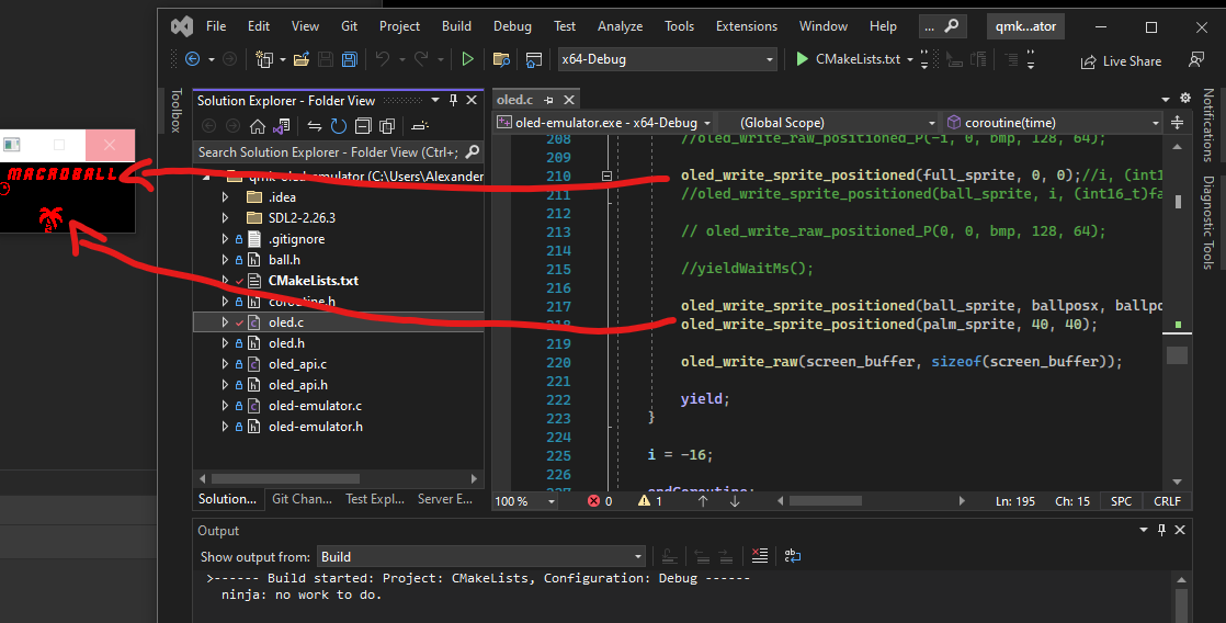
I started by trying to get a few simple words to display- it worked fine. Next I tried to get some images to display. This was a bit more fiddly, as the bytes of each image had to be in a certain format. I spent a while trying to optimise the way the pixels were stored and rendered.
To speed up the process, I made a little emulator for QMKs draw calls, so I could just test/see how my images and animations looked on my PC, without having to worry about compiling and flashing the firmware to the device.
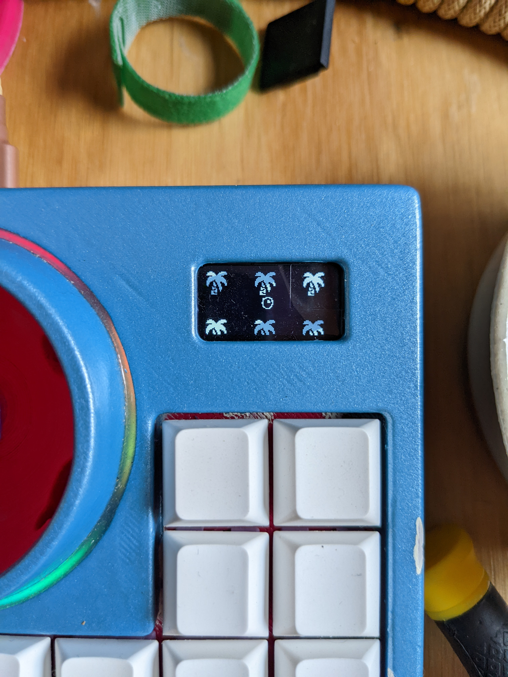
I also wanted to have some sort of animation- maybe a game- for fun, so I did a little work on the sprite rendering:
- Allowed sprites to have an “alpha” (see through) channel
- Allowed sprites to render partially off the screen (sounds super trivial, but doesn’t come out-of-the-box)
- Simulated a little XYZ coordinate system, so you can move sprites around, and in front of other sprites
- Added a sprite and animation format that was relatively lean, and made a little program that could spit these out
All in all, this was probably overkill, especially as it would have just been simpler to get a better processor (ATMega32s aren’t super powerful) and do things more simply, but the constraints were fun, and it worked in the end.
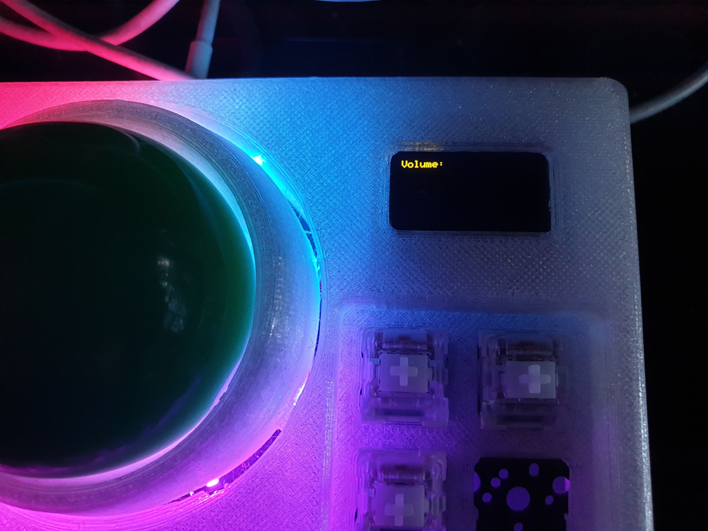
I then added a few things that were actually useful: a volume control, a CPI (trackball sensitivity) control, a trackball scroll sensitivity control, and of course, a minigame.
Lastly, I cleaned up the code a bit, and split the functionality out into “modes”. These are just little files and functions that say what the OLED and keyboard should do (e.g. “volume mode”). They can be switched (currently cycled with the encoder click), to jump to the next mode. I added a little transtition animation to make it look nice.
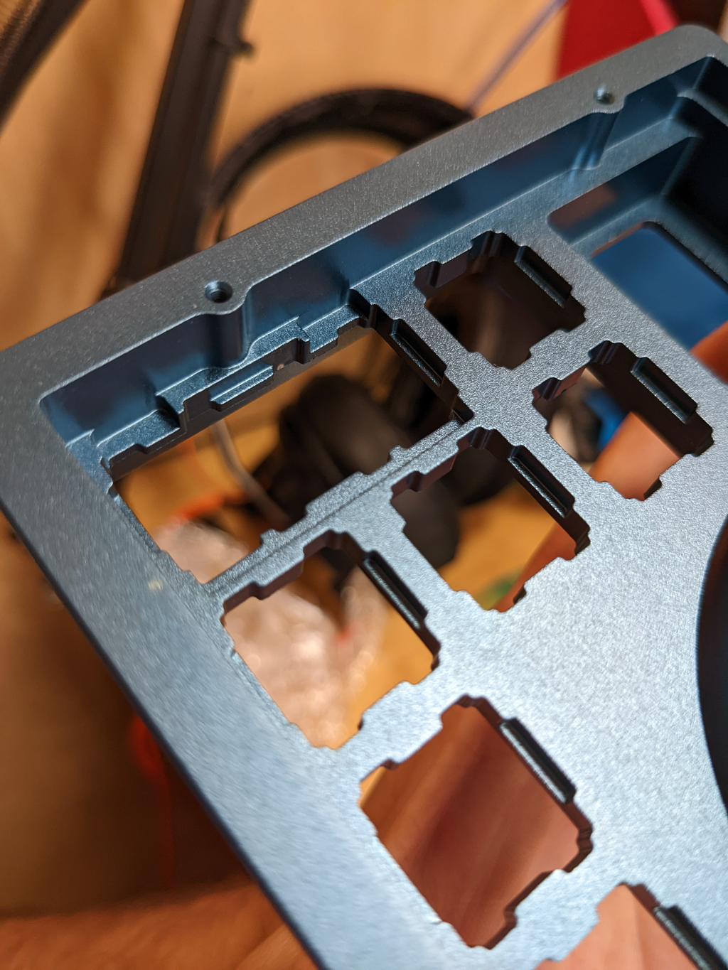
Plate and cutouts
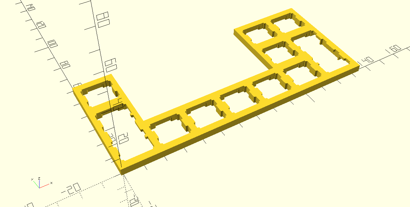
We opted to go for an integrated plate. Putting a separate plate into the build would’ve increased the price for a small run, as more parts add more setup costs. The unit’s plate design, being small and u-shaped, doesn’t gain the usual benefits of a separate plate, being quite rigid and not able to add much in terms of flex.
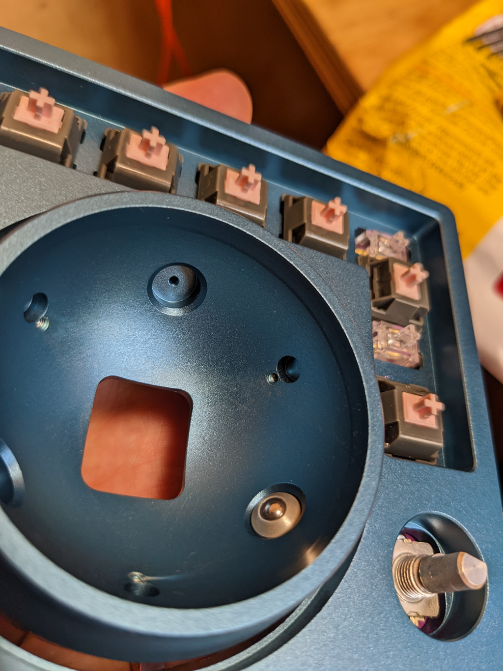
Going with an integrated plate, CNC’d out of aluminium, gave us the option to go with quite a hefty plate, 4mm thick. This was nice as it gave a bit more density to such a small unit. I followed the specifications from Cherry on their MX switches, along with some advice from the community, to get the switch and stablizer cutouts a tight fit.
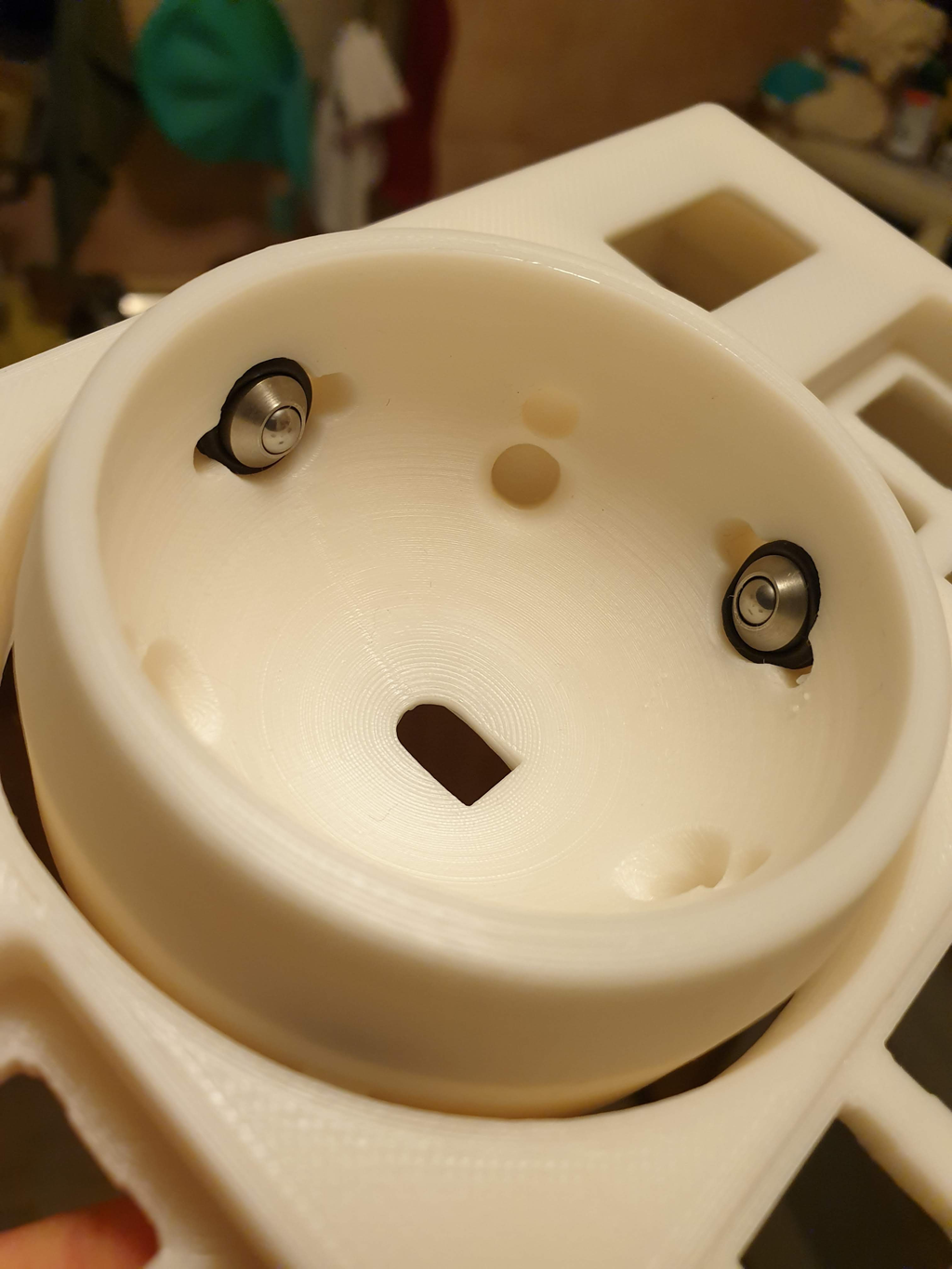
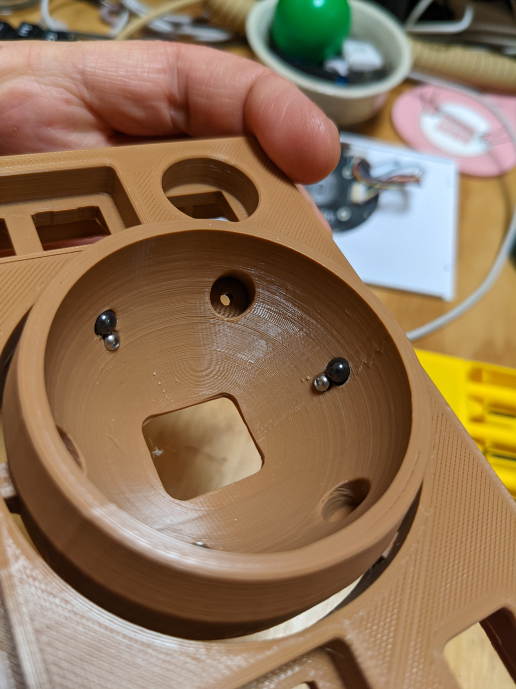
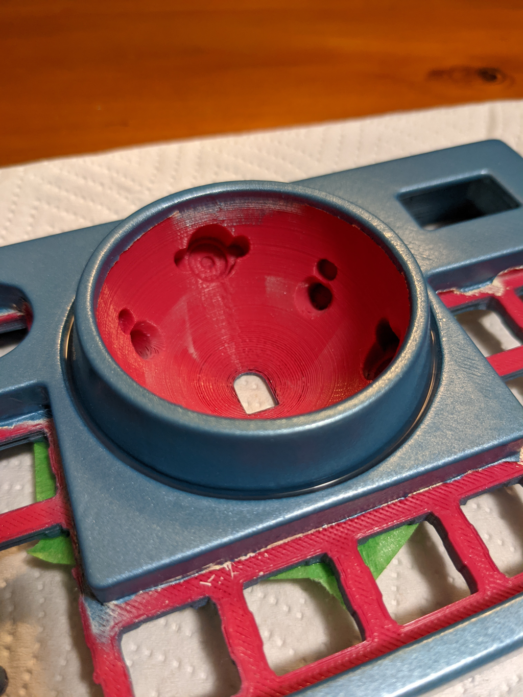
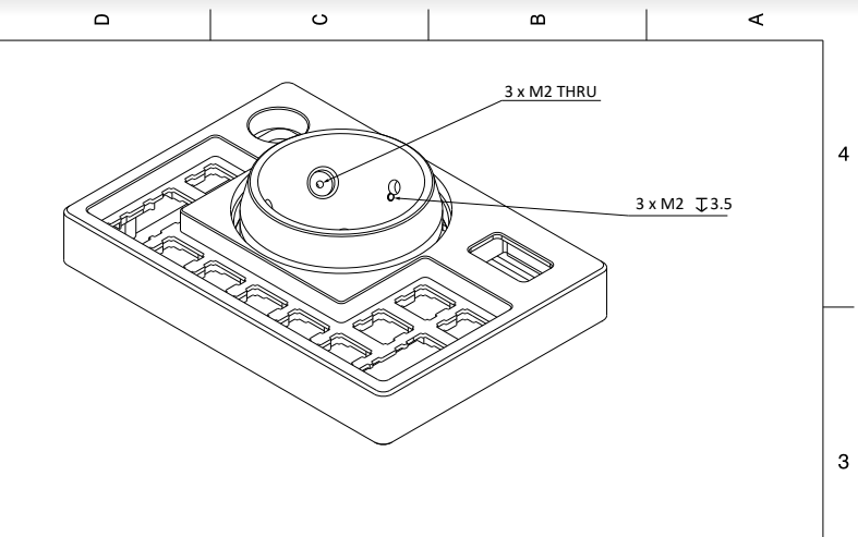
Mounting
Mounting the trackball was also a little tricky to get right. In the spirit of mechanical keyboards and their customisation, we decided to give a couple of different options. First, a static option, where three, smooth (e.g. silicon nitride, POM, etc), small balls are fixed to the main case with bolts, against which the trackball slides past. The second option was to insert threaded ball transfer units (BTUs), which are small balls that can spin freely atop several bearing, allowing the trackball to spin for quite a while, at the cost of noise.
LEDs
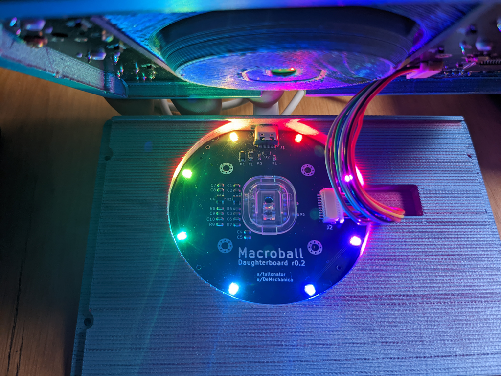
Back in 2021, lots of LED usage had moved on from backlighting and underglow, to bands and highlights.
So we decided to put our spin on it: a glowing ring around the trackball. While adding a few complications, and added a new part, a ring of CNC’d polycarbonate, it also added a bit of fun and flair.
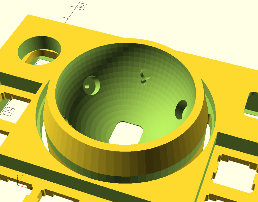
Manufacturing
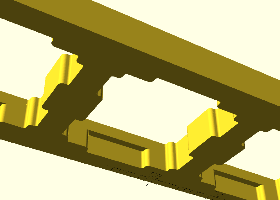
This was the first time I’d designed something for CNC, so it was a bit of a learning curve. For most of the 3D work I’d used OpenSCAD, which is great for being really explicit about measurements, as everything is in code, but it doesn’t export to STEP, which is a pretty useful file format for CNC machines. OpenSCAD also has a pretty limited feature set around describing bevels, chamfers, etc; if you want to pursue these, you have to write some pretty hairy code.
I ended up using FreeCAD as a stepping stone. FreeCAD has a module that allows that allows import of SCAD files, which I could then layer on some nice transfers to smooth out the hard corners, and then export to STEP, which I could then in turn send to the manufacturer.
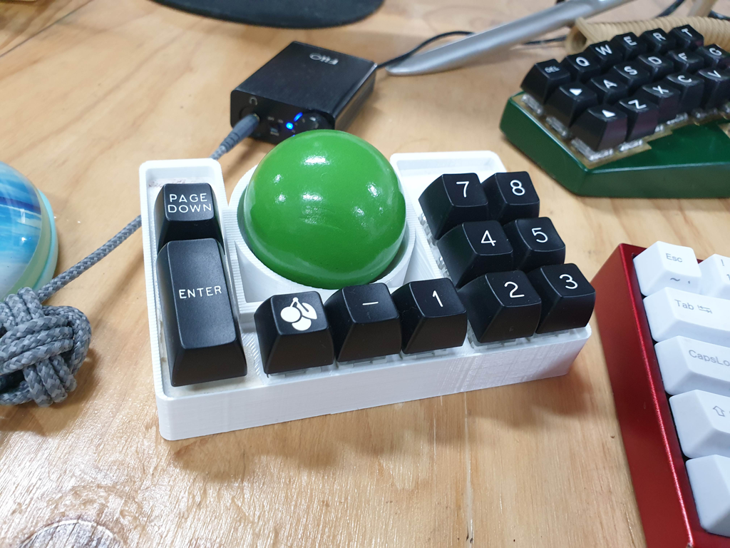
The final prototype came out pretty well. There are a few issues (I had to dremel the PC ring a little to fit 😬) that we’ll need to tweak before a final production run. But for a first go, I was quite relieved that generally it all fit together and worked.
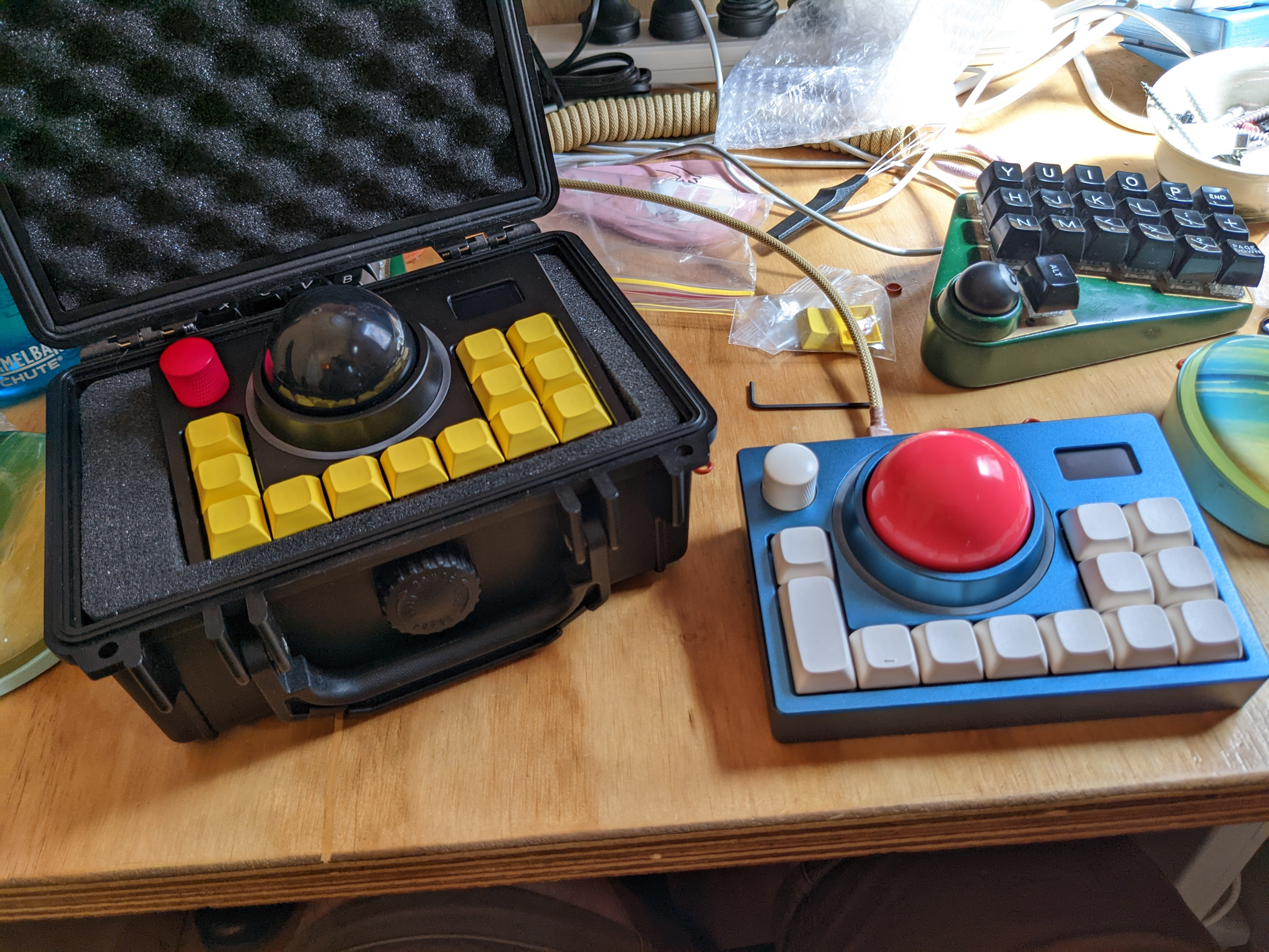
If you are intested in seeing more photos of the prototypes, jump over to the gallery. Or if you’d like one for yourself, please fill out our interest check and we’ll see if we can make it a reality.